
Page 10 - IFR_Book_Sample-2020
P. 10
IFR-Chapter-2-V10-BAK_Basic Master Frame.qxd 12/19/2019 4:13 PM Page 11
Chapter 2 - Your Flight Instruments: Behind the Panel 2-11
Understanding the Airplane’s Gust/Stress Envelope
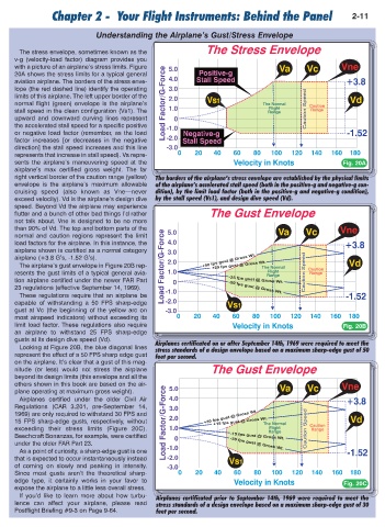
The stress envelope, sometimes known as the
v-g (velocity-load factor) diagram provides you
with a picture of an airplane’s stress limits. Figure
20A shows the stress limits for a typical general
aviation airplane. The borders of the stress enve-
lope (the red dashed line) identify the operating
limits of this airplane. The left upper border of the
normal flight (green) envelope is the airplane’s
stall speed in the clean configuration (Vs1). The
upward and downward curving lines represent
the accelerated stall speed for a specific positive
or negative load factor (remember, as the load
factor increases [or decreases in the negative
direction] the stall speed increases and this line
represents that increase in stall speed). Va repre-
sents the airplane’s maneuvering speed at the Fig. 20A
airplane’s max certified gross weight. The far
right vertical border of the caution range (yellow) The borders of the airplane’s stress envelope are established by the physical limits
envelope is the airplane’s maximum allowable of the airplane’s accelerated stall speed (both in the positive-g and negative-g con-
cruising speed (also known as Vne—never dition), by the limit load factor (both in the positive-g and negative-g condition),
exceed velocity). Vd is the airplane’s design dive by the stall speed (Vs1), and design dive speed (Vd).
speed. Beyond Vd the airplane may experience
flutter and a bunch of other bad things I’d rather
not talk about. Vne is designed to be no more
than 90% of Vd. The top and bottom parts of the
normal and caution regions represent the limit
load factors for the airplane. In this instance, the
airplane shown is certified as a normal category
airplane (+3.8 G’s, -1.52 G’s).
The airplane’s gust envelope in Figure 20B rep-
resents the gust limits of a typical general avia-
tion airplane certified under the newer FAR Part
23 regulations (effective September 14, 1969).
These regulations require that an airplane be
capable of withstanding a 50 FPS sharp-edge
gust at Vc (the beginning of the yellow arc on
most airspeed indicators) without exceeding its
limit load factor. These regulations also require Fig. 20B
an airplane to withstand 25 FPS sharp-edge
gusts at its design dive speed (Vd).
Airplanes certificated on or after September 14th, 1969 were required to meet the
Looking at Figure 20B, the blue diagonal lines stress standards of a design envelope based on a maximum sharp-edge gust of 50
represent the effect of a 50 FPS sharp edge gust feet per second.
on the airplane. It’s clear that a gust of this mag-
nitude (or less) would not stress the airplane
beyond its design limits (this envelope and all the
others shown in this book are based on the air-
plane operating at maximum gross weight).
Airplanes certified under the older Civil Air
Regulations (CAR 3.201, pre-September 14,
1969) are only required to withstand 30 FPS and
15 FPS sharp-edge gusts, respectively, without
exceeding their stress limits (Figure 20C).
Beechcraft Bonanzas, for example, were certified
under the older FAR Part 23.
As a point of curiosity, a sharp-edge gust is one
that is expected to occur instantaneously instead
of coming on slowly and peaking in intensity.
Since most gusts aren’t the theoretical sharp-
edge type, it certainly works in your favor to Fig. 20C
expose the airplane to a little less overall stress.
If you’d like to learn more about how turbu- Airplanes certificated prior to September 14th, 1969 were required to meet the
lence can affect your airplane, please read stress standards of a design envelope based on a maximum sharp-edge gust of 30
Postflight Briefing #9-3 on Page 9-64. feet per second.